|
|
|
||||||||
|
|
|
||||||||
|
|
....Building an MGB fuel injection twin throttle body manifold |
| Introduction | First Models | Sensors | Engine Management Basics | ||
| Requirements | Sub-systems | Tuning | Sizing Injectors | ||
| gas tank mods | Fuel supply system | My first ECU | F.I. Links - Sources | ||
| Special Project Wide Band Oxygen Meter | O2/Tach/Vac/Timing Logger | ||||
| Other peoples Triumph F.I. Installations/Projects | |||||
| Special Project Megasquirt - The Quintessential D-I-Y Fuel Injection ECU | |||||
| Building a Custom GT6 Manifold | Whitey's F.I'ed Spit6 Project | ||||
| Building an MGB manifold | Experimental twin bodies on a GT6 | ||||
| Building a twin TB MGB manifold | The other half of the story | ||||
|
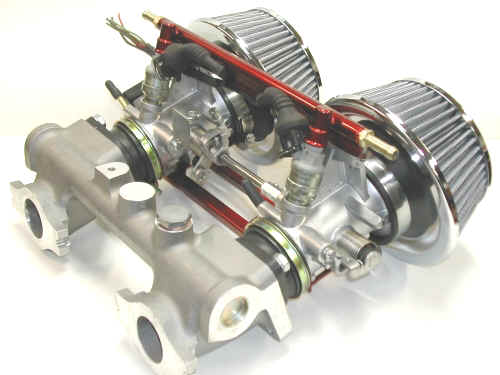
What I find the hardest in building these is simply settling on a fuel rail design. Mounting the bodies is not all that hard. The trick is the mechanical spacings and injector sizing issues to make sure the fuel will get where it needs to go in the right quantities. The hardest issue here to overcome, was the interconnect linkage between the bodies. Again, I'm basing this design on what was learned while building the manifold and fuel injecting my FIS6. This design is built on an off-the-shelf, brand new Dual HS6 MGB manifold. (found on EBay of course) This saved me a lot of work, as with 1.75" ports, I didn't have to port it myself to match the throttle bodies. This time around work started with simply reaming the mounts just a bit to match the carb studs. In the end I opted to use two bolts rather than studs and nuts. The real work was the fuel rail. The hardest design part, was the interconnect linkage.
|
|
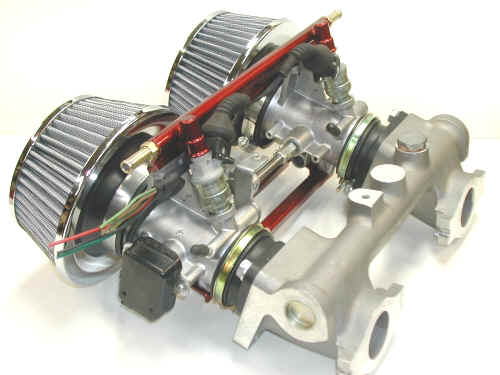
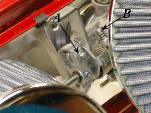
19lbs injectors were used. The injector harness plugs are from a BMW. The black box on the left, is the throttle position sensor. The fuel rail used the Duratec cups as before. A peice of L iron was welded to the1/2" id. fuel tubes to act as a mount plate and stiffener between the bodies. A custom lower body spacer was built to span the bodies from below.
|
| As mentioned before the throttle interconnect
linkage was the hardest part to design. It took some real brain smoke to
figure out how I was going to do it and still keep it clean. Pluls I
needed a way to be able to balance the twin bodies (just like standard
twin SU's or ZS carbs) but I didn't want to fight with balance AND
trying to get them to both pull at the same time. HA! Got
it! I'll just extend the shaft and move the inter-carb
adjuster back over next to the drive body. uh oh...sounds much easier
than it was.
|
|
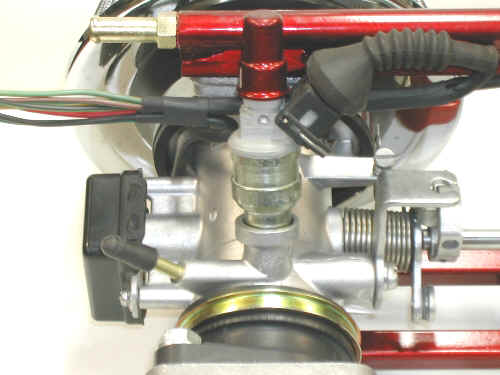
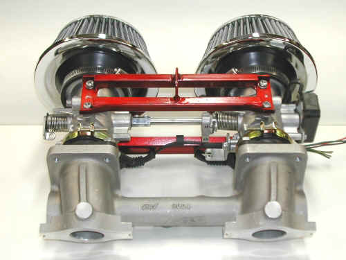
Screw A in the picture above, sets the inter-carb balance. B is the standard types of idle stop. The lever from the carb on the right, pushes against the back side of screw A. The spring behind the screw, is captive on a pin, and all captured inside the lever screw A is screwed into. The spring simply eliminates slop between the carbs. I'd LOVE to have this design on my MGBGT and on my stock GT6 as well! It would make balancing the carbs and throttle linkage soooo much easier. Lever A was originally pinned to the slave body butterfly shaft. After pressing out the pin, I redrilled it, and tapped it for 8-32 set screws. Since this lever needed to sit so close to lever B, I couldn't use the little rod cups like on stock SUs. So I drilled the drive body butterfly shaft, and pressed in a steel pin. I then drilled and reamed the end of the inter-connect shaft to simply slip over the pin as the pivot point. This is also why I couldn't re-pin lever A to the shaft, as the pivot pin filled the shaft where the lever pin would have needed to pass through the shaft. So two flats (one front and one rear) were cut into the shaft for the set screws (visible above in the bottom of lever A ) to lock it to the shaft. In the first and second pictures on this page, you can see the shaft connection to the slave body. I drilled out a thread-all coupler to match the shaft diameter. I then cross drilled it, tapped and inserted 8-32 screws to pin the shafts together.
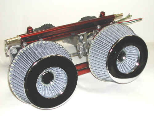
The air filters are 3" 'rice-rocket' units, off-the-shelf from Pep Boys. Since the TB intake is actually only 2.75", I wrapped the stepped flange with dense foam strips. Once formed, they were glued inside the air cleaner opening as a stepped platform to match the throttle bodies. 3" hose clamps are used (as designed) to hold the cleaner firmly in place. This entire assembly amazingly weighs in at under 6 lbs! The overall length from head flange to outer edge of the air filters is shorter than the stock carb setup with the metal can filter boxes.
|
![]()
©1987-2010
All material copyright© Teglerizer 1996-2008last edited
3/15/08

hits since last reset