|
|
|
||||||||
|
|
|
||||||||
|
|
....A solution to the Siamese port problem? |
| Introduction | First Models | Sensors | Engine Management Basics | ||
| Requirements | Sub-systems | Tuning | Sizing Injectors | ||
| gas tank mods | Fuel supply system | My first ECU | F.I. Links - Sources | ||
| Special Project Wide Band Oxygen Meter | O2/Tach/Vac/Timing Logger | ||||
| Other peoples Triumph F.I. Installations/Projects | |||||
| Special Project Megasquirt - The Quintessential D-I-Y Fuel Injection ECU | |||||
| Building a Custom GT6 Manifold | Whitey's F.I'ed Spit6 Project | ||||
| Building an MGB manifold | Experimental twin bodies on a GT6 | ||||
| Building a twin TB MGB manifold | The other half of the story | ||||
|
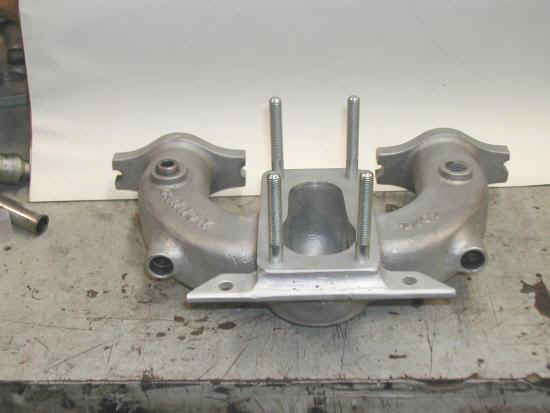
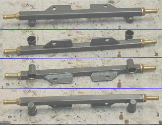
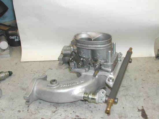
Well I've come up with yet another good candidate for such a setup on an MGB. My own MG BGT will be the test bed. I figure I should know what I'm doing at this point after fuel injecting my FIS6. This design is based on a Cannon Weber DGV carb/manifold setup. With considerations to clearance issues, throttle body availability, my own desires to be unique, and an eye on simplicity, .... I present the following rather simple and clean design. I started by simply welding two injector bungs into the legs of the manifold so they shoot straight down the runners towards the head. For the Megasquirt, two squirts alternating, should work just fine to keep an even fuel distribution going. I can always go up to four squirts, simultaneous if needed. Although the fuel rail mount is in this picture, the next step was the rail design. I cut the injector cups of a Ford Duretec fuel rail I grabbed at the local pick-and-pull yard. I like these cups as they have a short pipe out the side, making it easy to connect to a rail. After drilling to properly spaced holes, I silver brazed (56% silver) them into a 1/2" square steel section, right off the shelf at Home Depot.
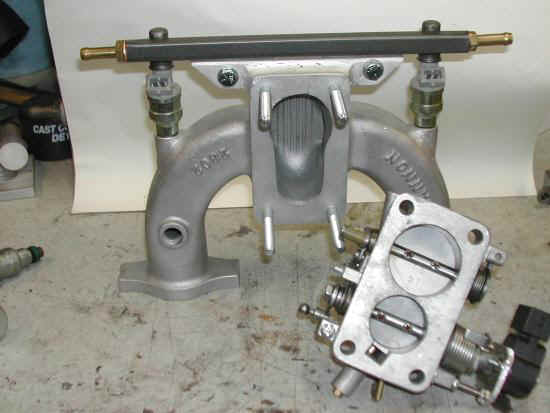
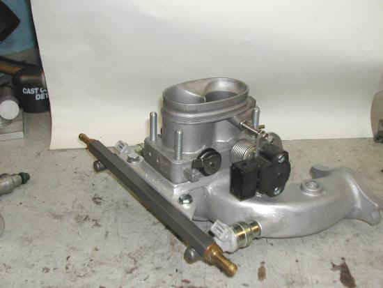
Once happy with the alignment, I started on the mount. The rail was stuffed on an old pair of injectors and eye-balled as to how a mount should be designed. As usual I got luckily with what I think turned out to be a quite clean layout. An aluminum bar was added to the underside of the manifold carb flange, and two steel ears welded to the rail. The rail was clamped in place and the two mount holes drilled. I had planned to mount a Honda pressure regulator right on the rail but decided against it for flexibility reasons. I prefer to use adjustable regulators, and can simply mount one on the inner fender well wit ha pressure gauge. I welded 1/4" thick squares into the ends of the rail, drilled and tapped them, and installed hose barbs with copper compression washers to seal them to the rail. After installing a set of imjectors, I clamped them in place and pressure tested the rail. A couple of hose clamps, a pressure gauge.... and it all held 90psi for about 4 hours with no bleed down. Yippee! A really amazing part of all this, (and one reason I decided to even try this) , was the accidental discovery of a component fit. I had wanted to use the twin butterfly progressive VW throttle body on FIS6 . Much to my amazement, that VW body fits perfectly on the Cannon manifold. When I say it fits, I mean it quite literally is the same bolt pattern as the original Web DGV carb! Where the Weber DGV is a 32/36mm butterfly configuration, this VW body is a 35/44mm. So I ported the manifold just a bit to match the butterflies. |
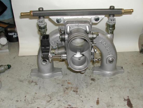
| The MKII Passat throttle body has a TPS already mounted on it. But the butterflies were simply way too big for a 1800cc MGB engine. I used that body as a model for where to mount a TPS. I cut off the outer spring from the primary butterfly shaft. I drilled a set pin screw to secure the inner spring spring collar to the shaft. I ground flats on the remaining shaft end to engage the Ford TPS I chose to use. A mount plate was made up and long 8-32 screws were used as standoffs to support the TPS mount plate.
|
|
|
|
|
|
|
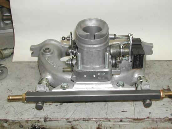
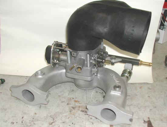
| Although the throttle body is oval shaped, it just happens to have a 3.1" circumference. A standard 3" air hose elbow fits fine. To minimize bonnet clearance issues a Cobra 90 degree boot was used for the air intake. |
|
|
| In this last shot you can
see the idle air bleed screw (brass screw in the end of
the protrusion in the center of the TB) the vacuum tap and Cobra
(low profile) air elbow. One last thing to mock up is the ECU
controlled idle air valve. I'll probably stick with a Bosch valve for
this installation as a simple hose connection to one of the two screw in
manifold ports will make for a simple hookup. Just like on FIS6
I'll mount the IAC sensor right in the heavy rubber boot right before
the TB. One large connector will be wired up to handle the
injectors, TPS and IAC
...stay tuned....
|
![]()
©1987-2010
All material copyright© Teglerizer 1996-2008last edited
3/15/08

hits since last reset