|
|
|
||||||||
|
|
|
||||||||
|
| Now this was a wild
one. I wanted to run crank triggered wasted spark. But what coil
setup do I use? I could have gone the EDIS route, but wanted full control
and 'revise-ability'. So once again EBay came to the rescue. It's a
great resource for studying the variety of things available to cover any
selected base.
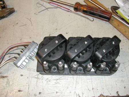
Since there isn't any room on the main PCB for two additional VB921 transistors, I decided to mount mine outside the main MS box. Plus I didn't want to have to mess with the power pulses or the lines switching these power signals in the harness. So I re-wired the single VB921 already on the board, as the driver for my electronic tach. I wired up a 74HCT125 buffer driver circuit in the prototype area of the MS box (version 3 board) to drive the lines feeding the coil drivers outside the MS box. I didn't want to bring the raw uP signals out without some type of protection. So with all this in mind, I went searching for a coil setup to use. In selecting a coil pack, I just happened to find one that included a wiring harness. This Oldsmobile three coil wasted spark setup was dirt cheap and came wit ha matching connector and chunk of harness. I also liked the way the wires came out the side rather than up and out on the axis of the plug wires like many do.
Now the cool part is, not two days after receiving this setup, I also found a set of brand new high output coils that match this setup. They are a full 45KV output.
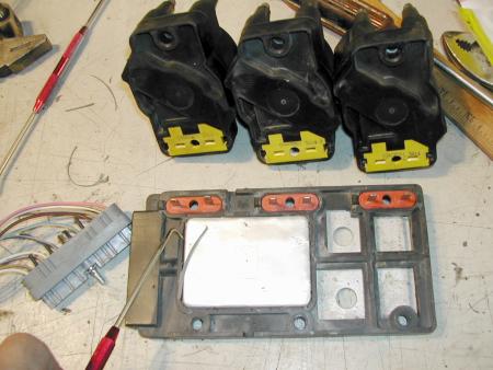
These yellow bottomed coils are the high performance versions. Thank goodness the MS has the dwell control. These coils have a primary resistance of only 0.35 ohms! A sharp pick was used to remove the small rim of rubber glue that held the lid on the circuitry. Now the cool part too was I had previously found a full schematic to this module in a Haynes manual at a local Pep Boys auto parts store. So I knew what I was in for here. The circuits have a bunch of dwell control stuff as well as a slew of other inputs that controlled when the coils fired, none of which I needed.
|
|
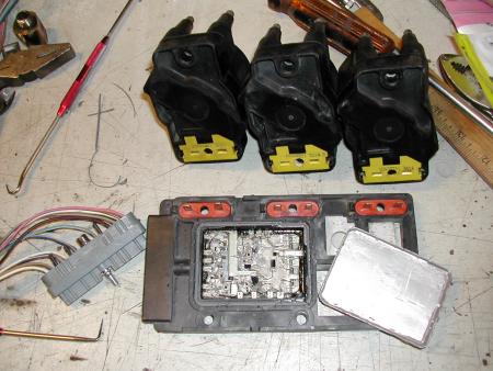
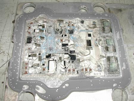
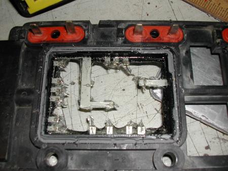
After cutting all the little leads going from the frame encased terminals to the circuit, I realized I probably could have simply used the power transistors that were already on the board. But I decided I'd gone this far.... might as well keep going and do it as I was planning.
You can see the three power transistors up the right side of the substrate. The entire circuit is covered in an unhardened, very thick Jello like compound. I guess perhaps this also added to my decision to not use this circuit.
|
|
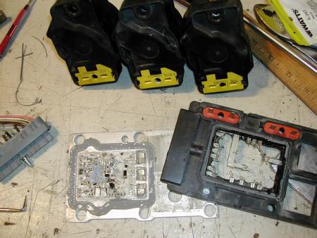
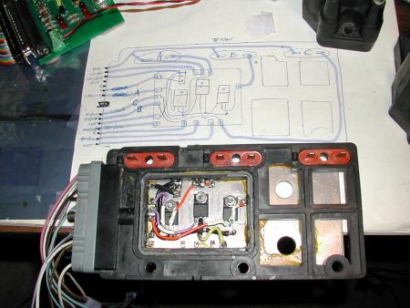
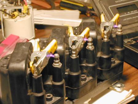
After tracing it all out, I used 3M Super Weather Strip Adhesive to glue (and seal) the metal back plate onto the frame. I mounted my transistors and wired it all up. A bunch of the wires weren't needed. If I had thought about it earlier, I would have mounted three individual 0.01ohm resistors in the box, and used those wires as extra current/dwell control monitoring terminals. This resulting setup, really surprised me. The documentation all says 5mS cranking, 3mS running, .1mS off. Going by my oscilloscope trace I had to cut it all the way back to 1.7mS running. This was at (or just after) the peak of current rise time. The secondary outputs are registering around 47KV.
That spark gap here is opened up to about .2" (in the pic above). The MS box is sitting at 6krpm (stimulator driven) rock solid spark! You can even see AND hear, the rev limiter kick in and start skipping spark events. The spark sound changes dramatically, as does the color. But the arc itself is straight and steady. So this setup should easily jump the plug gaps (2 x .035-.040) in normal operation.
|
©1987-2010
All material copyright© Teglerizer 1996-2008last edited
3/15/08

hits since last reset