|
|
|
||||||||
|
|
|
||||||||
Whitey - 1975 Spitfire Specific Tasks and Procedures |
||||||
|
||||||
|
5/2001
The Temperature Sensor Section
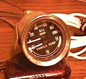
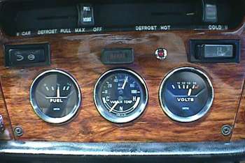
The reason the new dash was designed was so I could add a third gauge. I wanted to add an oil pressure gauge, but the Spitfire dash doesn't leave a lot of room to do so. My options were limited. I didn't want to give up any of the present gauges or cut another hole somewhere 'out-of-pattern'. So I opted for the Smiths Dual gauge that incorporates an Oil Pressure gauge and water temperature gauge in one casing. |
|
The model number I used is GD 1301/21. This particular gauge has the oil pressure on top and the scale numbered. The Water temperature is simply marked C-N-H. Center scale on the temperature gauge is pretty close to 180°F.
|
|
I simply swapped chrome bezels with an old fuel gauge, so it would have the same black painted ring as the rest of the stock Spitfire gauges. |
|
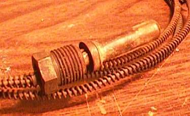
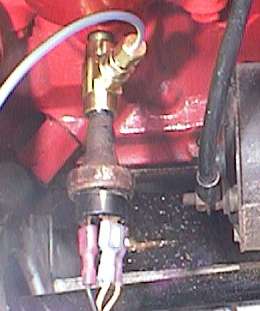
The temperature probe threaded boss will thread right into the stock temperature sensor location on the 1500 engine. The problem is there isn't anything to seat the sensor against.
To properly mount the sensor you need the adapter that is used (among other places) on the 1275 MG A-series engine. The standard 1275 A-Series MG Midget unit is what I used (part number 11K2846) Thread this into the block with a stock brass compression washer. Then thread the sensor into the adapter. The sensor clears the bottom of the thermostat without any problems.
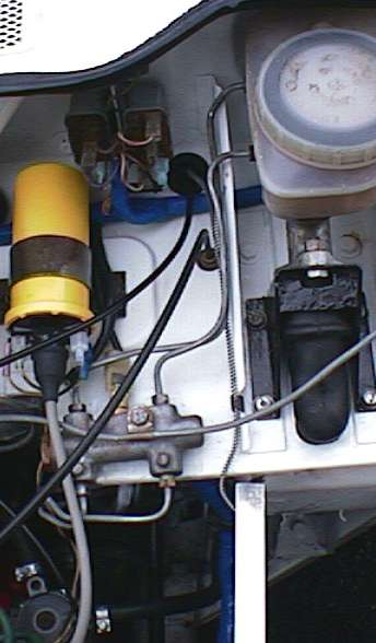
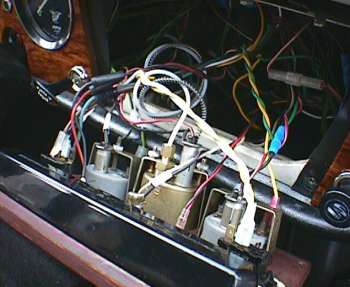
The temperature sensor is part of the gauge and can not be removed from the back of the gauge. I ran my sensor through the dash, and created a few 'loops' (like the clutch line for flex-ability) in the pipe to give me the ability to pull the dash without major flex of the gauge line. I ran it through the bulkhead at the choke cable grommet in the firewall. This brought the line out just under the horn and starter relays, and up along the support next to the brake master cylinder.
|
|
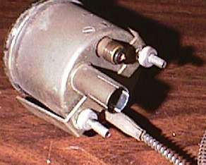
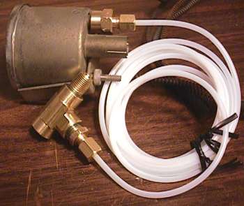
A stock Sunpro kit for
pressure gauges will thread directly onto the pressure port of the gauge. I used an o-ring
to seal the brass adapter onto the gauge. The engine end of the adapter is made from
standard 1/8" NPT threaded pipe adapters and a T, available at any large hardware
store. The fittings shown attached to the white line in the photo above came with the Sunpro
gauge kit. Not shown here, is the original pressure switch which will mount in the end of
the T, opposite the threaded adapter that will thread into the engine. The pressure line
will be threaded along the same route as the temperature line. |
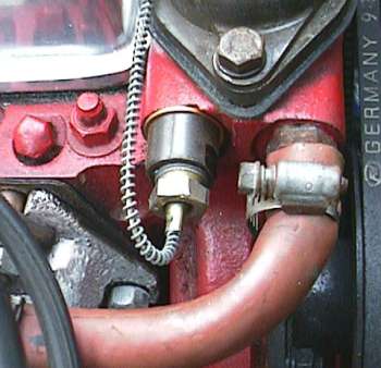
The adapter 'T' threads into the engine with the original pressure switch threaded into the homemade adapter. I left a gentle curve in the pressure pipe, allowing for engine movement without stressing the pipe. I ended up running the pipe along the route of the electrical harness and then up the firewall and through the same hole the temperature sensor runs through.
|
|
|
©1987-2010
All material copyright© Teglerizer 1996-2008last edited
3/15/08

hits since last reset