|
|
|
||||||||
|
|
|
||||||||
Whitey's Engine Rebuild
Whitey - 1975 Spitfire Specific Tasks and Procedures |
||||||
|
||||||
|
11/7/01
| Well putting Whitey's' engine back together
has been a real learning experience. I'm the type that likes to understand exactly how
stuff works. Diving into a project I've never tackled before does not scare me. After all,
If I really screw it up, I can always go back and let someone who DOES know what they're
doing, do it right. And in the meantime.... I've at least learned, what it is I'm paying
someone else to do for me. Although not totally flying blind here (I have done this kind of stuff to smaller engines,... 2 stroke motorcycles, lawnmowers, etc.) I figured how hard could it be. Well it's not. Trust yourself. Read everything you can find. Take your time. Hey..this philosophy worked when I tackled the O/D tranny rebuild in Whitey and it turned out fine. |
|
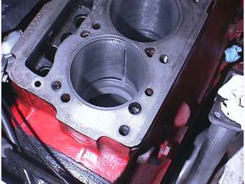
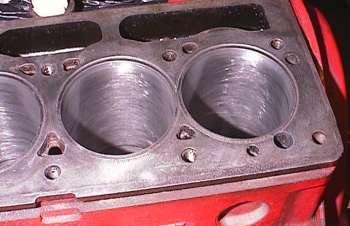
| First things first. Measure everything, TWICE. I
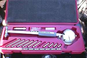
picked up a bore gauge (on EBay of course) so I could see what the bores were like. Were
they straight? ...need an over bore? What? Measuring the bores I found cylinder #3 (that actually had the low compression) was amazingly in better condition than cylinders #2, & #4, that still had good compression.
|
 |
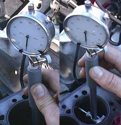
Each graduation on the gauge is 0.0005". I used dial calipers to set a 'zero' on the gauge at 2.9000". In the photo above left, the bottom of the bore still measured 2.900+/-0001". Above right shows a cylinder reading near the top of the bore at 0.0012". So it's actually reading 2.9011". |
|
|
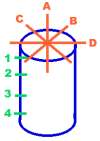
The Drawing at the left, is the positions in the bore where measurements were taken with the bore gauge. The letter measure 'concentricity, the numbers, the depth in the cylinder. I wanted to know if the cylinders were warped, and how 'oversized' they might be. I needed to know if I needed a bore and hone , or could get away with honing the cylinders and just installing new rings, etc etc. | ||||||||||||||||||||||||||||||||||||||||||||||||||||||||||||||||||||||||||||||||||||||||||||||||||||
| The dimensions in the
following tables are 2.900" PLUS (+) what's in the First measurements of the cylinders after initial piston removal.
|
|||||||||||||||||||||||||||||||||||||||||||||||||||||||||||||||||||||||||||||||||||||||||||||||||||||
rear
After initial honing of the cylinders to break the glaze on the walls and flatten them a bit, I noticed a problem. In the #4 cylinder. There was a very visible vertical 'groove' up the front face (towards the front of the engine). I could just barely feel it with my finger nail, and to the best of my abilities, the bore gauge said it was roughly 0.0007" deep. Much more visibly identifiable, than measurable because of the honing striations. After further honing this 'groove' has now almost completely disappeared. After honing the cylinders (three times), I'm leaving it at these dimensions. (Plus I'm getting better at using the bore gauge)
So if you look closely at the two tables, (ignoring my lack of skill reading the bore gauge the first time) The second table by comparison, shows the cylinders to much more concentric. Using a glaze busting three leg stone hone in a power drill, barely removed 0.0005" from the walls of the cylinders. |
||||||||||||||||||||||||||||||||||||||||||||||||||||||||||||||||||||||||||||||||||||||||||||||||||||
![]()
©1987-2010
All material copyright© Teglerizer 1996-2008last edited
3/15/08

hits since last reset


 front of
block
front of
block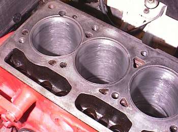 rear
rear